| Elise A/C Fix |
The following is the text from Lotus Service Bulletin #2005/01 and additional comments from Elise owners who have made the modification.
REASON:
To prevent evaporator icing and optimise AC performance.
The temperature probe for the AC system needs to be positioned at the coldest part of the evaporator, or the false signal provided my allow ice formation on the evaporator core, resulting in restricted airflow to the cabin.
In May 2004 (approx.) the heater/AC unit was revised to re-route the AC temperature probe (thermistor) from being inserted from the air inlet side, to being bracket mounted on the air exit side of the evaporator. The design of the bracket was subsequently changed to improve probe position.
Introduction (all VINS approx.)
| Rerouting of AC probe | Non-USA Elise: | '04MY VIN Serial No. 1948 |
| Exige: | '04MY VIN Serial No. 1957 | |
| USA Elise: | '05MY VIN Serial No. 0001 | |
| Optimised positioning of probe | Elise 5-speed: | '05MY VIN Serial No. 0666 |
| Elise 6-speed: | '05MY VIN Serial No. 0681 | |
| Exige: | '05MY VIN Serial No. 0653 | |
| USA Elise: | '05MY VIN Serial No. 0659 |
ACTION:
If a complaint of intermittent or poor AC performance on is received on any car in the above
VIN range, and diagnostic procedures indicate correct refrigerant chargin and system operation,
carry out the following check/rework procedure:
1. Set the heater control to full cold (to position temperature flap access).
2. Use the alarm transmitter fob to mobilise the car, and disconnect the vehicle battery whilst still mobilised (alarm LED extinguished).
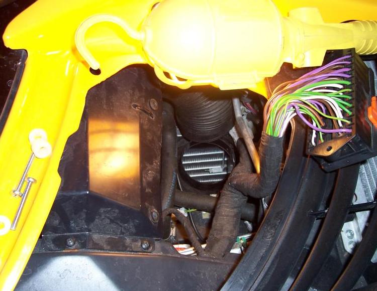
3. Remove the passenger side front body access panel.
4. Release the two retaining screws and cable tie and move the wiper motor cover with fusebox aside.
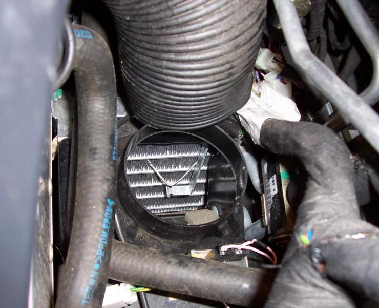
5. Remove or move aside the trunking between the heater housing and air distribution chamber.
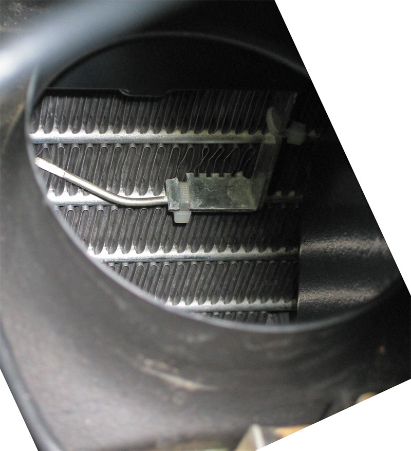
6. From within the heater aperture thus revealed, examine the position of the AC temperature probe. The optimum position is in the centre of the second from top row of evaporator fins, with the tip of the probe just touching the fins.
Two types of brackets have been used to route the probe capillary line, with the description relating to the distance from the top of the evaporator:
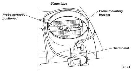
50mm Bracket (latest type):
Check that the tip of the probe is in contact with the evaporator finning. If not, carefully bend until
this achieved.
80mm Bracket (earlier type):
Cut the two cable ties securing the probe to the bracket, taking care to retrieve the remnants.
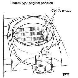
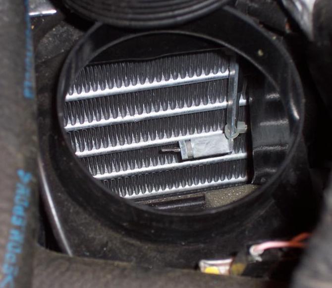
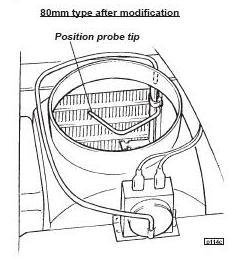
Carefully move the probe from under the bracket, gently bending the capillary line away from the evaporator
surface and positioning the tip towards the matrix lateral centreline, and in contact with the second from
top row of fins.
Both Bracket Types:
Ensure that where the capillary line exits the top of the heater casing it lies flat against the casing.
Otherwise, inadvertently disturbing this section during re-assembly or other operations may cause the probe
tip position to be disturbed.
7. Refit air trunking and wiper motor cover/fusebox.