By John Zender
PART 1 - THE HISTORY
I bought my first Lotus in 1982 when I was 22 years old. All I knew about Lotuses was that a high school friend said he always wanted one, and there was a cool yellow Europa that came into my self-serve island occasionally for $3 of premium.
The car I eventually purchased was a type 54 "low nose" Europa that was originally sold and owned in Germany. The car was brought to the U.S. in 1981 and owned by an older guy with a bit too much arthritis. I just thought the car looked cool and nobody else had one. For $4,500 I got a decent looking car with 50K miles, and a lot of bondo, rust, zip ties, and bailing wire included at no extra charge. The car ran reasonably well but most systems were on the verge of total failure.
Over the next 12 years I totalled the car twice, painted it complete 3 times, and had the body off twice for limited restorations. When you're in college, limited means that you try to make up for budget with a lots of labor and creativity. This includes learning the skills of fiberglass, paint, upholstery, and motor work. The car was nearly always a runner, and even commuted to San Luis Obispo on a nearly weekly basis during my first year at school. The lack of budget combined with my labor, however, always insured the Europa would be a reassonably dependable, decent looking car, with unmatched handling and a girlie motor.
The 54 was the ultimate handling car wrapped in a marginal package. I often dreamed of what the Ultimate Europa would be. The dream Europa would have the same handling of the current car with at least 150 hp, slick shifting 5-speed box, more leg and foot room, and hydraulic clutch. In addition, the car would be designed for ease of maintenance by eliminating and/or rearranging much of the hardware, and of course, it would have to be FLAMED. A trip to the Lotus gathering at Donnington park in '96 confirmed that such cars can be a reality. Richard Winters of Bank's Service Station had an impressive collection of heavily modified and well engineered S1's. Rich has done more with Europas than anyone I have met in my Lotus life. He has already done most any conversion and/or modification that one might consider, and is an invaluable source of knowledge. Banks designs and sells a wide variety of custom parts, including complete chassis and bodyshells of their own design
In March of '96 I began a serious restoration and conversion that would include all of the major changes mentioned above. In addition, other systems would be modified as budget, time and motivation permitted. My goal was to drive the machine to Portland for the West Coast Lotus meet in September.
I began the restoration without knowing which of 3 power units I would use: Lotus Twin Cam, Vauxhall 16V, or Cosworth BD. I struggled with the balance between cost, horsepower, availability, dependability, originality, and of course, leakability of the 3 candidates. According to Richard Winters, any of the power units can be fit into the S2 chassis if you're dedicated. The Ford block would be the easiest to fit into the Europa (especially if I converted to a Twin Cam Chassis), and would look proper in the S2. The Vauxhall motor was a much more modern design that doesn't leak and can be easily tuned up to 260 hp. When a Twin Cam parts car became available locally with a Cosworth BDR and fresh 365 gearbox included, the decision was made.
I had previously owned a Europa Special with the weird shifting 365 and couldn't bring myself to install such a linkage on the ultimate Europa. I decided to use a Renault NG3 Gearbox from an '82 Turbo Fuego. This is a side-shifter 5 speed that I knew was proven to at least 260 Hp in the Banks cars. I had no trouble locating a unit with 80K miles for $300 at a local junk yard. I was able to sell the 365 (less the output shafts and bell housing) for a about 3 times the cost of the new box, making the conversion even more attractive.
PART 2 - Chassis and Drivetrain
The first part covered rebuilding and conversion of my Type 54 Europa. In this part Ill explain the details of the changes I made to the chassis and drivetrain.
Finding the Twin Cam parts car with the BDR Cosworth dictated much of the design for the Ultimate Europa. The chassis, motor, brakes, and much of the suspension and drivetrain would eventually find their way onto my S2. Of course, countless miscellaneous parts would also be pilfered from the donor carcass over the 6 month conversion. The flared carcass itself, of course, is headed for bigger and better things as the first Euroadster.
The Cosworth motor is a stubborn squeeze into an S2 Europa chassis, but fits perfectly in a Twin Cam frame with no modifications. Fitting the S2 body onto the later model chassis, however, is not quite so straightforward. The later chassis has a 1" longer wheelbase, and has a wider "Y" section in the rear that interferes with the early body. I accommodated the rear frame section by widening body tunnel about 1" on each side where it blends into the rear bulkhead. The widened tunnel of course, interferes with the seats which must also be notched before they can slide all the way back.
I had often considered the possibility of increasing the length and width of the footwell to accommodate my size 11 hiking boots. Since the donor chassis was heavily damaged and badly repaired, I decided to go for it and cut off the front cross member and fabricate one of my own design. The rear vertical surface on the new cross member is moved forward 2" on the drivers side only. To maintain the original suspension geometry and hardware, this necessitates cantilevering the rear A-arm pickups. The cantilevered pickups are strengthened by box sections fabricated of 1/4" thick steel that surround the pivot bolt guide tubes. The lower portion of the X-member is also extended forward 3-1/2" to improve stiffness of the structure. This extension provides a horizontal surface for mounting of the steering rack clamps, allowing easy adjustment of bump steer. The new X-member also incorporates a 12" long backbone section that is narrowed by 1" on the drivers side to allow a wider footwell. The new backbone was constructed of 1/8" steel sheet to improve its stiffness as well. I cut through the backbone of the donor chassis 12" behind the front cross member and attached the fabricated piece. I located the new X-member 1" back from its original position to create a Twin Cam chassis with an S2 wheelbase.
Once the new backbone/cross member section was joined to the Twin Cam frame, the footwell section of the body was extended forward 2" and inboard 1" to take advantage of the notched chassis. The larger footwell made it easy to fit a new Tilton 3 cylinder pedal assembly thats mounted under the bonnet inside the plenum. The pedal bracket is bolted through the body and into threaded bosses welded to the top of the chassis cross member.
Other minor modifications that were required to fit the Twin Cam chassis included moving the shifter and body mounts (the ones behind the dashboard) back 1". I also glassed-in new seatbelt/body mounting bobbins in the tunnel to line up with the Twin Cam style threaded body mounts located between the seats.
Although the 365 gearbox that came with the donor car was in excellent shape, I couldnt convince myself to use it. The combination of 60's technology, parts supply, and most importantly, the strange linkage required to operate a rear shift box made it impractical for the Ultimate Europa. Instead, I acquired a Renault NG3 box from an 82 Turbo Fuego. This box is a side shifter 5-speed that closely resembles the 365 but is newer design with better ratios (no huge gap between 4th and 5th). To use this box with the Europa drivetrain, you must replace the output shafts with the ones from the 365. This is a direct swap that requires no special tools or machining. The output seals, O-rings, spacers, and threaded collars from the 365 must also be swapped out since the Fuego hardware is set up for CV joints. A nice option is to use the Fuego collars along with the 365 seals. The NG3 collars incorporate a large O-ring to seal the threads, but must be bored out to accept the Lotus-type output shaft seals.
The Fuego does not incorporate a pilot bearing in the flywheel, but instead, uses a roller bearing mounted in the bell housing. The simplest way to mount the NG3 to the Ford block, therefore, is to build-up the original Twin Cam bell housing with weld metal, and then bore it to accept the Fuego input bearing/seal assembly. The original Fuego input shaft can be retained, and fits into the ford clutch without modification. Dont forget to remove the original Ford pilot bearing though, since it may interfere with the end of the input shaft.
The Fuego transmission shifts from the right-hand side, but because of the location of the Ford oil pump, the shift linkage must run down the left-hand side of the motor. This, necessitates moving the shift shaft to the left side. To accomplish this, I welded an extension to the left end of the original NG3 shift shaft, and made a seal holder for the shaft to exit the rear gearbox housing. The seal holder was welded directly to the rear tranny cover on the left hand side, and a aluminum plug was welded to the right to cover the hole original hole. I fabricated a custom shift linkage that follows the basic design of the Lotus 4 speed system and has a standard H pattern with reverse next to 2nd . The linkage took about 4 iterations to make it right, but the car now changes gears extremely well (much better than any other Europa Ive driven).
The changes I made to the footwell,
pedal assembly, and shifting have improved the driveability of the Europa
dramatically. The car is more of a pleasure to drive and much easier to
drive fast. For myself, the amount of labor was worth the payoff since
I plan on keeping the car forever. In the next part Ill discuss other
modifications to the car including leak-free windshield mounting, hydraulic
clutch, and changes to the suspension, wheels, and brakes.
Part 3-rear suspension and brakes
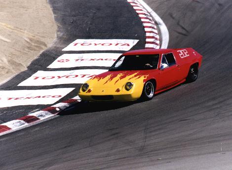
In October, I finally had the car sorted enough to trust it on the track. What a blast! Simply the most fun Ive ever had driving a car. Ive been on a track about 6 or 7 times with my Esprit S2 and Europa S2, but nothing compared to this last session in the UR. The car has always handled well, but that extra 100+ horsepower really makes a difference in the fun factor. Being able to power up the hill into the Corkscrew and blow past other cars on the straights was a thrill. The track, however, did show some limitations of the car. The rear brakes suck!
I decided to upgrade the car in stages starting with the rear suspension and drivetrain. I wanted to run 4-pot rear disk brakes, get rid of the original hub/bearing/axle assembly, and remove cornering loads from the driveshafts and gearbox. I also wanted to move the rear track inboard 2" overall so that I could mount 7 x 13" 4-spoke Revolution wheels that wouldnt fit inside the original bodywork. I considered using the original upright and boring it to fit Corvair or other axles. The original box-section trailing arm, however, does not leave enough room inside the wheel for an opposed-piston caliper. This necessitated changing the trailing arm to a thin, tubular type and using a lower A-arm and wide based upright to hold the toe. A top link swinging off a new chassis cross member would take up the corning loads.
In order to begin this project I needed a suitable rear upright to start with. I knew that Earl Beyer had been using Formula Ford uprights on his TC Europa for several years with good results. These uprights were manufactured for the Dan Gurney Eagle Formula Ford cars that ran in the late 70's. The Eagle parts have similar geometry to the Europa and are not much heavier than the Europa counterparts. I purchased the last two new uprights from a guy at Sears Point who also has all the original Eagle tooling including the patterns to make more uprights. These pieces were designed to run with stock VW bug axles, bearings spacers, and a VW Type III hub machined for whatever lug pattern you desire. Its interesting to note that one of the original VW bearings is identical to the Europa (#6206), and the other is a roller bearing. The Eagle cars, however, use two of the Europa type ball bearings and are supposed to be very dependable. The VW axle/hub/spacer/spline arrangement is also nearly identical to the Europa. How come they dont blow up like Europas?
Before disassembling the car, I carefully measured the original features of the stock suspension and developed a scaled CAD drawing that located the axle centerline, track, and lower link inner pivots on the bell housing. I also measured the change in camber at 2" bump, 2" droop, and 4" droop (-1.3o, +1.0o, and +2.0o respectively from ride height), with the intention of emulating this movement with the new design. I then designed the lower A-arm incorporating the narrowed track, wider wheels, and new uprights. To determine the length and location of the trailing arms, I set the chassis level, and bolted up the new A-arm and upright. I then set the upright plumb and level and measured from its front lugs to the forward trailing arm pivots.
After building and installing the dual trailing arms, I cut-off the rear chassis just ahead of the axle centerline, and installed a new cross member. I clamped the top link inner pivot to the cross member so that I could rotate the suspension and measure the change in wheel camber as it moves through its arc. Clamping the pivot in place allowed me to easily measure the change in camber at different locations. I was surprised to discover that very small changes in the location of this pivot made large differences in the camber change especially at full bump and full droop. When I found the sweet spot that most closely followed the original Chapman movement, I welded the pivot in place.
During this entire design phase I worked
on the left-hand side of the car only, and kept the original hardware hooked-up
on the right side so I could make comparisons and measurements as required.
When I finish the brakes and driveshafts and have everything fitted, Ill
duplicate a set of parts for the right-hand side.
Part 4 - More Rear Suspension and Brakes
The work talked about in this story was completed last April and Ive put a couple thousand miles on the car since then. In December I disassembled the car again to begin Phase 4 which will include a full roll cage, vented front rotors, all new wiring, and some miscellaneous bits.
In Part 3 of Building the Ultimate Europa I had finished design of the rear suspension and fabricated prototype hardware for the left hand side. A quick review of the changes include new Formula Ford uprights with lower reversed A-arms, single top link, and 2 unequal length semi-trailing arms.
I optimized the forward trailing arm pivot locations through a series of trial and error experiments. I tack welded the front pivots as far forward on the frame as possible with the arms horizontal. Using a bump steer gauge I measured the change in toe-in through the suspension travel, and then repositioned the pivots and tried again until I found the best locations. I settled on a geometry that gave about .002" toe-out during the first 1/2" of bump, and then about .010" toe-in through the next 1-1/2" bump. The idea here is to produce mild, increasing understeer as the suspension is loaded in a turn.
The car came together in March and April with completion of the driveshafts and brakes. Special halfshafts were required to bring power from the Fuego box to the VW CV joints at the outboard ends. There are a few different ways to go about fabricating a shaft like this using various combinations of components. I chose the simplest option and built mine using a Europa U-joint yoke and a VW axle. I started by first annealing the VW axles. I then cut off one end and turned its diameter down to fit into an original Europa TC splined yoke (the one that the roll pin normally goes through). I fit the axle such that it slipped through the splines I.D. and protruded about 1/8" on the U-joint side. Having the axle stick through allowed me to place fillet welds on both sides of the yoke to produce a very robust connection.
Welding was not as straightforward as I hoped. In order for the joint to be heat treatable after welding, a high carbon alloy filler rod such as 4130 is required. When 4130 was used, however, the welds would continuously cold crack immediately after welding. The high carbon filler rod combined with the very high carbon axle produced a weld that was extremely brittle. To solve the problem, I welded the first pass with a low carbon steel (E70S-2), and made subsequent cover passes with 4130. Dillution of the axles steel with the low carbon filler produced a crack-free first bead. After welding, the axles were slow cooled in the oven, and then brought back to the heat treater for quench and temper.
I purchased a pair of Wilwood Dynalite 4 piston calipers with 1.375" bore to mount in the rear. Since the Eagle uprights have no provisions for caliper mounting (the Eagle used inboard disks) I needed to modify them to accept the calipers. To achieve this, I carved 1/2" thick mounting plates out of 6061 aluminum and welded them to the uprights using 4043 filler rod. After welding, the uprights were re-heat treated to a T6 condition to regain the strength lost by welding. I had custom 10" solid rotors and aluminum mounting hats fabricated to complete the brake installation.
The car performed very well on its maiden voyage to Dave Bean Engineering. Since then Ive had a chance to tune-in the geometries a little more precisely and have been rewarded with a definate improvement in handling over the old setup. The original S2 Europa handled excellently, but when I first added the Cosworth, TC chassis, Fuego box and 7" wide wheels, there was always a pronounced bump steer in the rear that I wasnt able to tune out. The new design has virtually eliminated this annoying handling quirk, inspiring more confidence in the twisties, and giving a much more stable ride at speed.
Besides the improvement in rear bump steer, the brakes are awesome and I can finally fit those wheels that have been sitting downstairs for 2 years. Also, the piece of mind Ive gained from eliminating the original rear hub/bearing setup should make me infinitely more relaxed on long drives and rough track sessions.
Part 5 - Rollcage and electricals
The latest installment of this continuing (and nearly completed) saga of Europa contortions. This latest conversion includes larger ventilated front disk brakes, all new electrical system, fuel cell, and a full roll cage. Along with Phase 3 comes a new overall direction with design of the car. The new plan is to make an SCCA certified Europa racecar thats still streetable and very dependable. Before I get into the meaty details, Ill review whats been done up to this point.
The car is a 1969 Type 54 (low nose) Europa. Ive owned the car since about 82, but began serious modifications in March of 96. Phase 1 consisted of replacing the original Renault powertrain with a 1730cc Cosworth BDR and 5 speed box from a Turbo Fuego. Also included in Phase 1 were the installation of a modified Twin Cam Chassis with an enlarged drivers footwell (1" wider, 2" longer), Tilton pedal assembly with balance bar, flush glazed (non-leaking) windscreen, hydraulic clutch, 4-pot Willwood front calipers, and a somewhat controversial paint job.
After driving the car like this for a year I decided that its gonna have to get more rear brakes. I tried all sorts of different slave cylinders, drum widths and lining material, but the brakes continued to suck. I decided that the car would have to have rear disks, and I really wanted to go "all the way" and fit a 4-pot caliper that I was sure would be enough. After many hours of measuring and head scratching, I figured that theres no way to fit an apposed piston caliper back there and retain the original box section trailing arm (unless you flare the fenders and move stuff outward). Anyway, all the head scratching evolved into Phase 2 which included Eagle Formula Ford rear uprights, 4-pot Wilwood calipers, 10" disks, and formula car suspension with CVs and upper links.
During the track event at LOG 18 last year the rear brakes worked so good that it allowed me to bias-in a lot more front brake. Of course this immediately cooked the original 9" front rotors. Besides this, the wall at the bottom of the hill at Road Atlanta was frightening going by at 100 mph. I knew I needed to improve the front brakes and make the car safer. Additionally, I had always wanted to redo the dasboard and rewire the car?..and so begins Phase 3.
After being refused by 3 different race shops to build a roll cage for my car, I bought a tubing bender and started it myself in December 98. Within a week I figured out why none of those shops were interested in building my cage. What a huge job! I knew that building a full cage in a Europa that allowed the body to be removed was going to be a major pain, but figured I could do it in a month if I worked on it 10-20 hours a week. Well, 3 months later I finally finished after putting in 150+ hours (Im glad I didnt keep track - itd be too discouraging). Before I started the cage I figured I could make a couple bends, then fit and mark it, then make some more bends and just fit as I go. -NOT- The main hoop, roof halo, and front downtubes had to be bent completely to shape before I could get them through the door and check the fit. If it wasnt close enough, I had to start over. I ended up bending all of the main tubes 2 or 3 times each to get em to my liking. To give you an idea of the learning curve here, I purchased at least 120' of tubing and probably used about 50 in the car.
Now that the cage is done, however, I guess Im glad I did it myself. Anybody I know whos had a cage built has always complained that it doesnt fit quite as well as they planned, or interferes with this or that. Because I knew what I wanted and was willing to do it over a couple times, it came out pretty good. I figure that skill and practice will get your bends within about 1/8 to 1/4", and getting any closer is mostly luck. Another thing that I learned while building the cage is that symmetry of the original Lotus body is outawack by ½ to 1" through-out , which doesnt make things any easier.
I followed the SCCA rule book and used 1-1/2" diameter seamless steel tube with .095" wall thickness for all of the required bars. This includes the main hoop (behind the seats) and diagonal, roof halo, front down tubes, rear braces, diagonal door bars, and removable horizontal door bars.
I stole some ideas from Mike Schlichts Europa racer and added a considerable amount of "extra" tubes that dramatically increased safety and stiffness of the cage. These extra bars probably added another 30 lbs, but after driving the car, Im certain that the weight penalty is worth the increase in stiffness and stability of the car. The extra tubes allowed me to fully triangulate all four corners of the chassis and tie them into the cage, backbone, and body. Each front corner is triangulated by running a tube from the front lower wishbone pivot to the bottom of the front down tube, and another from the pivot to the down tube near the bottom of the dash. Another triangle is formed by bars running from the same wishbone pivot, diagonally rearward and inboard to a plate in welded in the backbone (directly under the dashboard). Another bar runs from this same plate, straight across the floor, and into the bottom of the front down tube. Another pair of crossmembers run diagonally behind the seats between the top of the backbone and lower end of the main hoop. A single tube is also welded in-between the two front down tubes and supports the bottom edge of the dashboard. A diagonal brace connects this tube to the original dashboard/body mounts in the backbone. Two more horizontal bars triangulate the rear section by connecting between the main hoop near the door latch, and the chassis/rear diagonal brace junction. All of these "extra" tubes are thinwall (.065) seamless tubing.
The cage is permanently built-in to the body and is bolted into the chassis at 11 points. The connection to the lower front wishbone incorporates the original 1/2" pivot bolt. All of the other connections use a 1/8" steel plate welded into the chassis with grade 8 nuts tack-welded to the backside. The mating plates on the cage are also 1/8" thick steel with three 5/16" bolts each. In the rear of the car, the body is bonded directly to the rear diagonal braces about 6" ahead of the shocks, and the braces bolt into the chassis forks a few inches further back. This design was necessary since the rear of the chassis was shortened by about 12" to accept the new formula type suspension, eliminating the original rear body mounts.
Along with the cage I added a pair of 5-point harnesses. The shoulder belts are connected to horizontal bars running behind the headrests between the two large diagonals. I had Tonys Upholstery in Burlingame redo the original seats with slots in the cushions and headrests to allow passage of the anti-sub and shoulder belts.
After completing the cage I moved on to the electricals. For as long as Ive owned the car, the entire Lucas mess was junk. Over the years Ive replaced or redone most of the connections and at least 30% of the wires. Ive also had quite a few minor smoke leaks and a couple of really major smoke leaks. Add to that my lack of budget, soldering ability, and quality assurance over the first 10 years of ownership, and you end up with a car where you cant trust anything that uses electrons. I was fed-up with piecing the electrical system together, and finally wanted all my gauges and switches to work. A full re-wire was required. I had never attempted this before, but knew it would be difficult to trace all those strands and get the proper colors... so I decided not to. My first step was to rip out the entire harness - every single wire- cut it into little pieces, and throw it in the garbage. While I was at it, I took all the gauges and switches and handed em off to some poor soul so Id never have to look at em again.
The first plan was to buy a new complete set of Smiths gauges to keep that "original" look, but hey, plans are meant to change. Instead, I opted for a set of Auto Meter Phantom gauges with black bezel, white face, and red needle. I purchased all electric gauges so I wouldnt have to deal with capillary tubes running through the "quick release" dash. I replaced all the dash and column switches with nine high quality toggles. You know the type - you turn em on and they go on, you turn em off and they go off! (Very non-Lucas-like)
I took a lead from Daren Stone and bought individually labeled wire from Enos Custom Components in San Luis Obispo. This is pretty cool stuff. Its printed every 4" with the component ie starter, headlights, wiper, etc. Daren previously installed a similar wire set in his monster truck, and were both very satisfied with the quality and functionality of this stuff. Part of the re-wire plan included making the entire dashboard quick release so that I can pop it out to change a bulb or work behind there. To achieve this, I mounted the new blade-type fuse block in the front luggage compartment, and used two large military style circular bulkhead connectors through the rear wall of the compartment. Two pigtails with mating plugs run off the back of the dashboard and plug into the sockets. Since the steering column is now mounted to the roll cage (instead of the dashboard) I can unplug the dash and remove it in about 10 minutes! The new dash board itself is fabricated out of 1/8" thick 5052 aluminum. I had the surface "grained" on a large belt sander, and then black anodized and silk screened with white lettering. The dash screws into the rollcage along its bottom edge with six 10-32 flatheads, and utilizes the original four mounts on the top edge (retrofitted with 10-32s).
Another necessity for phase 3 was upgrading the front brakes. In phase 1, I installed the 4-pot Wilwood "Dynalite" calipers on the original 9" rotors. The first set of rotors I ran with these were cross-drilled and cracked badly within about 10 laps at Laguna Seca. The second set were a little thicker (.370) and not drilled, but they went into melt-down at Road Atlanta (LOG 18). I decided to go as large as possible with the new setup while still fitting into my 6x13 Revolution wheels with the original uprights. After a few more ferocious measuring and head scratching sessions, I ordered a set of 10.25 dia x .75 thick ventilated rotors and a new (wider) pair of Dynalites. The caliper mounts I constructed in Phase 1 were made by cutting the "ears" off the original forged steel bracket, and welding-on and extended section in its place. The new section was then machined and drilled for the new caliper. For this conversion, however, I decided to make a billet aluminum bracket to offset weight gained by the larger rotors. I had recently added a mill to my shop and was strangely eager to build such a part. Well, I hope I learned a lot about machining by making those 2 brackets... I started a total of 6!! Something I definitely learned when building the first bracket was that 10-1/4" rotors dont fit in this wheel/caliper combo without moving the steering arm inboard a lot. Oh well, Frey Racing was nice and gave me no hassle on the exchange. I ordered a set of custom 10" disks that were due to arrive only 2 weeks before WCLM!
Another major safety component required for the Ultimate Europa is a certified fuel cell with flexible bladder and foam filling. The original aluminum fuel tanks that I built for Phase 1 no longer fit the body anyway (because of interference with the rear cage members). To get the maximum quantity of fuel to fit under the horizontal rear bar, the front of the fuel cell would have to be angled sharply forward to follow the rear bulkhead under the passengers seat. I built a welded aluminum can of 1/16" 5052 aluminum with an open bottom, and a separate 1/8" thick aluminum bottom plate that pop-rivets in. I cut the various holes where needed, and sent the whole thing off to Fuel Safe for a custom bladder. Frey Racing helped me out a lot and got a 5 week leadtime reduced to 1-1/2 weeks to make WCLM.
Besides all the major changes I also kept myself busy adding aluminum front hubs from Dave Bean Engineering to further offset the heavy rotors. I also disassembled the motor one more time and changed all the seals and bearings.
I stayed up all night before the WCLM and almost got the whole thing put together --- but all the important stuff was ready, and I did get it on the track and had a blast.
Now that Ive driven the car a bit Im thoroughly stoked! For the first time, in my own mind, it really does seam like the Ultimate Europa. I get an amazing rush each time I drive the car. Everything about it - from getting in - to the squeeze of the 5-point harness - to the sound of the cambelt behind me - and, of course, the way it drives, all feel like "racecar". After a track session I let about 15 psi out of the tires, crank the shock dampening to minimum, and it drives like a Cadillac. OK, maybe not like a brand new Caddy, but maybe like the lowrider down the street with busted springs.
I never imagined the comfortable, confident feeling that I would get from not worrying about all the past smoke, flames, and faulty switches that always felt like theyre on their very last cycle. And what about gauges that bounce, flicker, and bob when theyre working, but just kind of lay there most of the time? Its so nice to turn the headlights on without having to jiggle the switch just right, and be able to start the car without the ignition switch turning in the dash and flaming, and ...shall I go on?
The roll cage also inspires lots of confidence when passing monster trucks and pit walls, but most noticeable is the improvement in the feel and handling of the UR. The first thing I noticed is that the car is much easier to drive straight on fast roads. The UR has had a pronounced rear bump steer ever since completion of phase 1. The new rear suspension of Phase 2 reduced the symptom by about half, and the cage has virtually eliminated it. Both on the straights and through long sweepers, I notice that the steering requires less corrections to hold it on line. Although I never got totally up to speed at Thunderhill, Im sure this trait is going to make it much easier to drive fast on the track.
Throughout building of the UR other Lotus peoples would often ask how much it weighed. With the roll cage, iron engine block, and bigger brakes, I figured I probably gained a hundred pounds. To my surprise, I finally corner weighed the completed car and found its only 1560 lbs with 3 gallons of fuel! I guess all those parts I "forgot" to put back on the car made a big difference. Why would you want an emergency brake in a Europa anyway? Any emergency you might have in a Europa isnt going to be avoided with that thing.
So the car is finally very close to what Ive imagined for the last 15 years. All the major conversions are complete and one more iteration might just finish it off. Hmmm.... a 2 liter motor and fuel injection might spruce up that engine compartment a bit. Watch for a debut of phase 4 next Spring, until then, watch your mirrors and stay out of the way!