| Worm and Wheel Limited Slip Differential |
By Kiyoshi Hamai
Chapman Report - November 1989
You've watched the light turn green and then those marvelous streaks of rubber are left behind those Formula One McLarens, Lotus and Ferraris. The rear ends wag a bit, and those two wide strips of molten rubber are imbedded into the pavement. You don't think anything of it, but try that same trick in your Lotus and... no can do. One streak of rubber, but two? How's it done?
You ponder the technical and conclude, Limited Slip differential... That's the trick! Yes, you're correct, limited slip diffy's, but not the type to which we're accustomed. The conventional limited slip diffy often uses friction clutch plates or even welded spyder gears! The avid Lotus nut will have heard about Salsbury limited slip diffy's. These use a friction clutch pack to limit the amount of speed differential between each half of the driven axle. Such diffy's often require special lubricants (all that friction creates lots of heat) and constant maintainance, adjustment and replacement of the clutch packs.
The off roaders and the road racers learned about a new type of limited slip diff that used only gears, no parts that slip, no more adjusting, just drive.
Enter the Worm Gear and Worm Wheel differential. First designed by Vernon Gleasman, then sold to Gleason, who marketed the first of this type of diff under the name of Torsen. Today, there are variations of the basic design being marketed under a variety of names, but the concept remains the same.
The worm and gear diffy unit simply replaces the spyder gears and ring gear carrier. It is a straight bolt in replacement part. But, the results are nothing short of amazing. Gone is the typical spinning of the inside rear wheel when attempting to exit a corner under power. For myself I can see those precious seconds ticking away while I wait for the rear tires to settle down so I can get on the throttle.
With a worm and gear diffy corner exits are smooth, with a touch of oversteer (power induced with BOTH rear wheels spinning!). My speed down those straights are not only higher but, reached more quickly.
Unlike a locked diffy, the worm and wheel diff allows for some differential action. When cornering, the outside wheel of the driven axle must travel a greater distance, thus spin faster relative to the differential housing. However the inside wheel must travel a shorter distance, thus slowing in the same proportion. The worm and wheel diff allows for this action to take place without subtantial resistance.
Now, when a condition is encountered where one wheel on the driven axle has less traction than the other wheel, a conventional differential will allow the wheel with the least traction to spin or increase its RPM relative to the opposite wheel. Unlike conventional diffs, the worm and gear diff prevents the wheel the loss of traction from spinning. Instead the torque is transferred to the wheel with traction.
The situation of corner exits is a combination of loss of traction and cornering. The worm and wheel diff is capable of slowing the inside wheel and simultaneously transferring the power to the wheel with more tractions, the outside wheel.
So, how does all this magic work? Well, honestly it's difficult to explain, but once you get it you'll know (and be hard pressed to explain it to anyone else).
Basically the worm and gear diffy uses a principle of machines; a worm gear can turn a worm wheel, but the worm wheel is not capable of turning the worm gear. The reason for this is the pitch of the gears. LIke a very steep ramp that is easy to slide down but impossible to clumb up, the pitch of the average worm gear is such that the worm wheel can't spin it.
This can be altered. If the pitch of the teeth were altered, so that our worm gear become more like a barber pole, then out worm wheel could spin our worm gear because the gear ratio is not so extreme. It would be like a push-type screwdriver or drill. These use a barber-pole like screw thread that, when pushed, spins the tool.
What Gleasman did was experiment until he determined what worm gear pitch would allow just a little bit of this push-drill effect. And this is used in the center of the worm and wheel differential. In this manner some differential action allowed, but not a large amount.
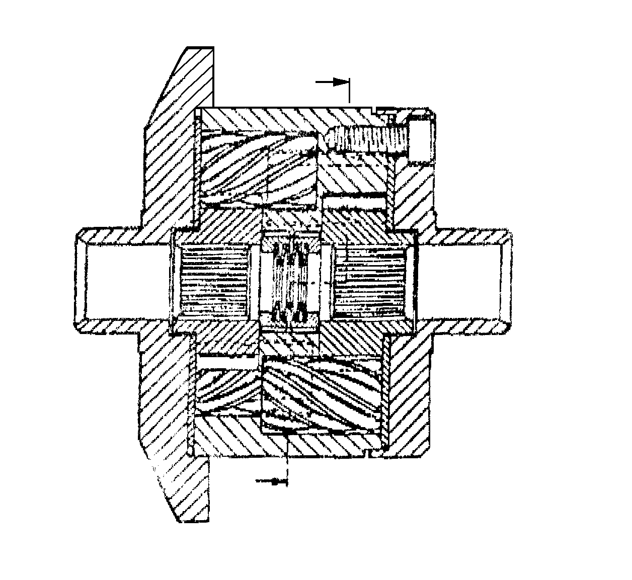
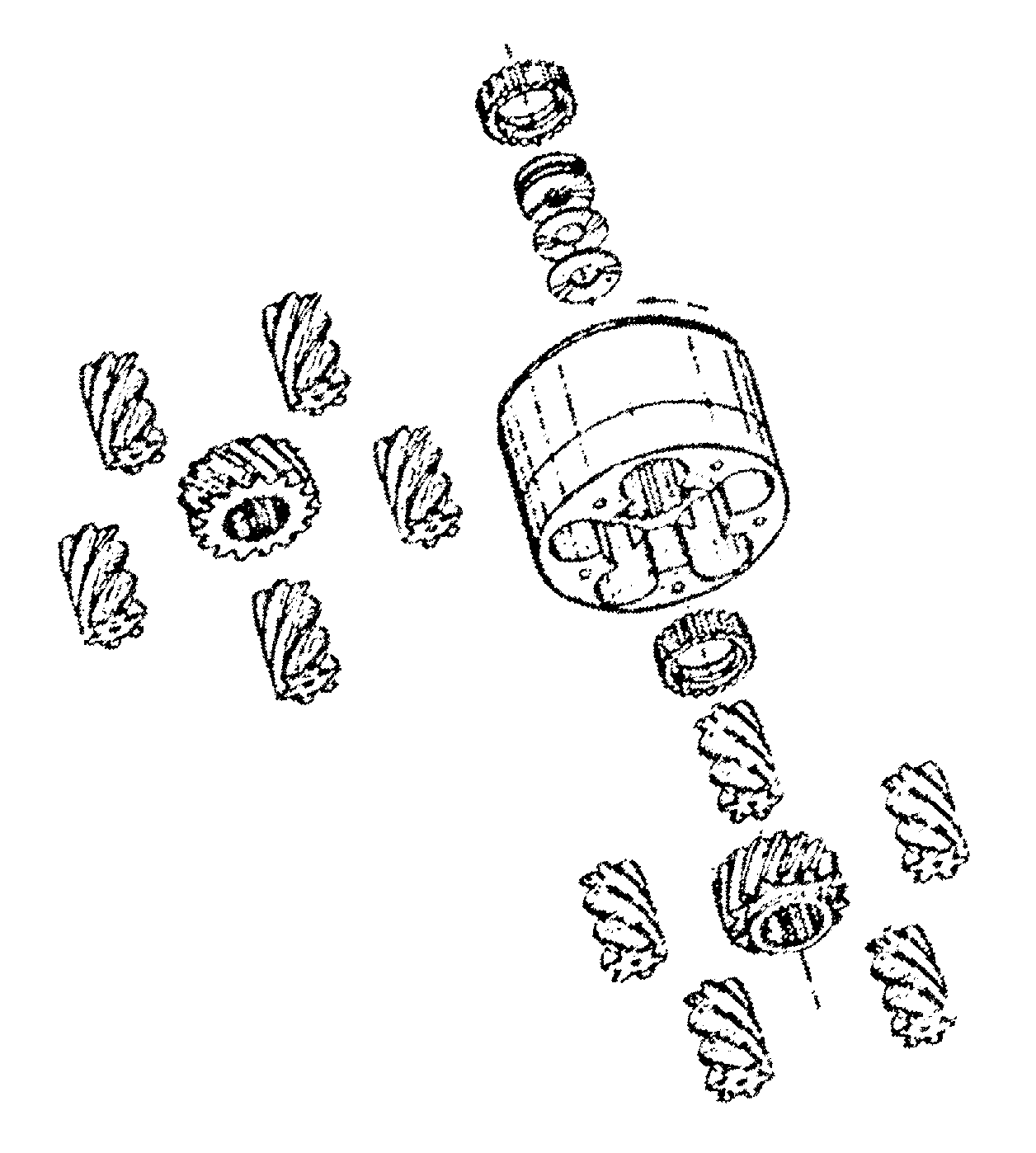
By the diagram you see a collection of meshing gears. At the center, connecting to the output axles, are separate worm wheels for each axle shaft. These worm wheels are mated to, in this case, five worm gears. Each worm gear is linked by a spur gear at the center of the assembly.
So, how's it work? In concept the differential is really two diffs in one. As the carrier is turned by the ring gear, it forces the worm wheels to rotate with it. Because the wheel is unable to turn the worm gear, this transfers power to axle shaft. However, the worm wheels of each side are connect via the spur gears. It is these spur gears that provide the differential action.
In a corner when differential action is required the inside axle slows, slowing the worm gear to which it is attached. This in turn twists the worm wheels in which it is contact. As these worm wheels twist they turn the spur gear. The spur gears are mated in such a manner that they turn each other in opposite directions. So, as the inside spur gear slows, it speeds up the outside spur gear which in turn twists the outside worm wheel. Normally, twisting the worm wheel has not affect upon the worm gear. This where the ramp angle of the gears come into play. Like the twist drill, the worm wheel and worm gear angles are cut to allow a certain amount of this twisting of the worm wheel to turn the worm gear. Thus as the inside axle slows it forces the outside axle to increase its speed by a like amount. The result is perfect differentiation while maintaining power to both wheels.
Because of the carefully selected gear angles, there is some resistance to all this motion. It is this resistance that creates the limited slip nature of this diff. By changing gear angles, the ratio of differential action can be changed.

When one wheel looses traction, a conventional diff would allow the wheel with the least traction to spin or increase its RPM level relative to opposite wheel. Like before this increase in axle shaft speed twists that wheel's worm wheel, which turns its spur gear. However the spur gear in mesh with spur of the opposite axle shaft and attempts to slow it. But, the opposite axle is in good contact with the pavement, and thus resists being slowed by the axle shaft with the loss of traction. Hence the spur gear of the axle shaft with good tractions will resist being turned by the spur gear of the axle without traction. This prevents the wheel with the loss of traction to increase it speed relative to opposite wheel. Power is automatically distributed proportionally to both wheels reflecting the amount of traction available at each wheel.

The typically the result is a bit more oversteer, power induced, and no inside rear wheel spin on corner exits. Lap times fall, corner exit speeds are higher, speeds attained on straights is therefore higher and the driving line can be altered, usually requiring a later apex due to higher corner exit speeds and power induced oversteer.
Although the worm gear and worm wheel diffs have been available for a number of years of many other cars, it's only been within the last year or so that these diffs have been developed for English Ford axles. This means these diffs are available for Lotus Elans, Sevens with Ford axles, Cortinas, Lotus Cortinas, Anglias, etc. List price I've seen is somewhere around $800. This compares to a Salsbury limited slip diff at $600.