|
By Kiyoshi Hamai
Chapman Reports - a series in 1982
PART 1 - THE BEGINNING
I purchased a Series 2 Seven in restorable condition. One of things I wanted to do was learn about the history of the
car since I was having thoughts about vintage racing the car. It was kind of like finding an orphan and trying to find out what its roots were.
There was intrigue and entertainment, none of which I expected when I towed the car home. From the papers I got with the car I located the
second owner in Michigan. And learned…
The car had entered the states in Detroit as an SCCA kit. The first owner's name was Roger Lemoore, who built up the kit and
proceeded to run the car on the street and drive to his local SCCA regionals, stripped off the windscreen, slapped on some numbers and went
racing. He raced the car at Kentfield and Waterford. That was between 1963 when the car was completed and roughly 1966. It was in 166 when Fred
Carpenter bought the car. Fred drove the car on the street one week and decided it was unfit for such use and used it for racing only from then
on. The car was painted very dark BRG and often mistaken for being black. Fred had the car repainted in a lighter shade of BRG. Fred raced at
Waterford, Grattan, Elkhart Lake,, Kentfield to name a few. At the time he competed in C-Production and later in D-Production. In about 1969 Fred
landed some sponsorship dollars from the Hush Puppy folks, you know those fuzzy shoes. I guess someone thought a Seven looked like a Hush Puppy as
the car was FLOCKED in olive green fuzz. One rolling Hush Puppy shoe!!! One of Fred's final races with the car was at Michigan International
Raceway in July 1972 where he finished 5th in DP with a fast lap of 2:05 and speed of 86.69 MPH.
It was soon after that the car was sold to a Jeff Lance who immediately stripped off the green fuzz and painted the car a
taxi cab yellow. As near as I can tell Jeff raced the car for a couple of years and then sold the car to someone in Arizona by the name of Tom
Davies. This was around late 1974 or very early 1975. Davies painted the car yet again, now in silver and lunched the original 1340 Ford Cosworth
engine and stuffed a 1600 Pinto block under the original Cosworth head.
After about 2 years of fixing this and replacing that, Davies got fed up and consigned the car to an auction company. The
auction company brought the car up to San Francisco, or actually to the San Mateo Fairgrounds in Sept 1976. The little old Seven was listed as
item number 234, between a '37 Packard Business Coupe and a '41 Ford Pick-up. The auction was asking $3200 of which Davies was to get $2750.
From that point until Damien Martin bought the car in spring of 1978 is a mystery, only the Seven knows. It is rumored that
were at least 3 owners during that period. Damien drove the car for the better part of a year until one day the twenty year old well raced gearbox
packed up and stopped. That put Damien into a rather awkward position, spinning into a guard rail backwards. Needless to say Damien started to
fix the damage and completed about 50% of the job, but enthusiasm ran short and the car sat and rusted for 2 years in Damien's garage. That's
when I stepped in and purchased Seven SB1246.
PART 2 - TEAR DOWN
The car was towed home. Or should I say trailered on Wally's all purpose Seven trailer. Once off loaded the first task was a
COMPLETE top to bottom inspection of just what I had bought! Hmmmm… Was this really a good decision? Only time would tell. The inspection
brought to light such things as the front end had been crunched at some distant time, the chassis was twisted slightly, the aluminum was getting
old and battered looking as if it had endured too numerous battles over the last 20 years. The skin was beginning to simulate Swiss cheese with
many areas having uncountable number of holes drilled. The list grew and grew and grewwwwww… I suppose I could have sort of just slapped
things back on and the car running in a couple of weeks or so. But, it wouldn't be very pretty, nor very reliable. More than likely had I done
that I would be spending the better part of the next years mending this and fixing that. So, I made the big leap and decided to go the whole way
by entering into a trek called TOTAL RESTORATION.
The first step was raise the car off the ground. You take out the jack and slip it under the car, right? No, wrong, not with an
engine-less Seven. You stick your hands under the chassis rail and bending your knees you heave and lift the sucker off the ground and then slip one
knee under it so as to free one hand to reach for that jack stand that you positioned exactly 1/2 inch out of your reach.
Anyway after a fashion I had the car in the air. The wheels came off, I unbolted the suspension, removed the rear axle and then
started drilling and chiseling off the rivet heads so as to strip the chassis of the aluminum skin. Within a period of 4-5 hours I had a dirty,
rusty twisted pile of tubes in my garage that was once a Seven.
I was really amazed at the speed with which a Seven could be totally dismantled. Next it was decided that the chassis should
be stripped of all the different coats of old paint. A large 1/2 gallon can of Jasco Deluxe Paint Remover was purchased. I have found this paint
remover to really work in the past. It has a gel-like consistency and softens paint quickly. A word of warning, be sure to keep this stuff off
polyester clothes and your skin. I wear a shop apron and rubber gloves and brush it on with a cheap brush (I toss out the brush after use). You'll
know when it comes in contact with your skin. At first you'll feel nothing, but after a couple of minutes you'll feel this burning sensation.
It'll be as if your skin is on fire! Don't rub! Rinse the area with liberally with water as the remover is water-soluble.
I used the entire half gallon to strip the chassis. I would apply, let it soak, scrape with a putty knife, hose off and let
dry. I went back and hit the stubborn areas with course sand paper and then re-applied the remover. The alternative is have the chassis sand
blasted.
Now, I was ready to inspect the condition of the chassis - welds, tubes, measurements, etc. My plan was to replace tubes
that needed reconditioning and then reinforce the chassis per my discussions with Wally Sinclair and others. I knew that considering how I
was planning to use the Seven that if the chassis were not strengthened it would surely fail. Consider that the Seven was originally designed in 1956
when the chosen engine had a peak output of 65 BHP and race tires were only 4 inches wide and hard as rocks. Now I was thinking of at least 135
HP and race slicks that were 8 inches wide.
PART 3 - CHASSIS INSPECTION AND MEASUREMENT
So, here was this old bare chassis in my garage, twisted, rusted, rotting, cracking, rattling and full of holes. I set up a
crude frame rack on my garage floor. I used a number of wood pads of various thicknesses to create a level platform (1" thick plywood). I
set the chassis on top of this platform and then drew parallel chalk lines on each side of the chassis (chalk marking string). These were to be my
reference lines.
I had noted that front end had been rebuilt. And, the chassis refused to lay flat. It was clear that it was twisted. I
located the centerline of the chassis and made sure that it lay parallel to the lines drawn on the platform. Longitudinally the chassis seemed
square. I next checked for lateral squareness, this was accomplished by measuring the distances from the forward pick ups diagonally to the rear
pick ups. Comparing these measurements, left versus right, the measurements should be the same. This was confirmed. Then all the pick up
points need to be measured in 3 dimensions. The chassis should be symmetrical left to right.
It was good news and bad for the chassis. It was square and parallel, but it was twisted. It rocked from corner to corner,
about 1/2 inch out. This was not that serious since it is possible to twist the chassis by HAND by grabbing the front and holding the rear
stationary. This just was not acceptable. I knew that if I want this car to handle proper the chassis needed to RIGID. Now, I understood why Sevens
were called flexi-flyers!!! They WERE!
The story about the Seven chassis is that Chapman built a chassis where it was completely triangulated and then began
removing tubes until the chassis sagged and then had the crew replace the last tube. By the looks of it that story was not far off. I counted no
less than 16 un-triangulated bays! The common practice for space frame construction is that every bay must be triangulated. Additionally, there
were no good pick-up points for seat belts, tranny mounts and weak steering rack mounts and radiator mounts.
PART 4 - CHASSIS RESTORATION
I brought in a number of Seven consultants to have them take a look at the chassis. Seven specialist, Seven Autocross
Champion, Wally Sinclair; ex-restoration surgeon, Brian Johnson; everyday commuter, Grant Larson; and Seven owners, Fleming Larsen, and Brandon
Burke. At first there was a lot of shaking heads. But, after hearing numerous ways of repair, reinforcements and modifications, I realized that
I had as many "plans" as people I had consulted!
Needless to say I decided to set about creating my own set of modifications, blending all of the suggestions I had received.
What I did next is rather humorous, but frightening too! I literally twisted the chassis by sticking a long pipe across the front, bolting down
the rear and twisting it! As I did I tried to watch and identify the areas that were flexing the most. No surprise, the un-triangulated bays were the
major culprits.
I have attempted to draw some sketches of the modifications I used. All added tubes were of mild steel and were either 1"
square or 3/4" round tube. All joints were mitered and shaped to fit. To allow for slight shrinkage during the brazing the tubes were cut tight.
The seat belt mounts were made of flat steel bars brazed together along their length. If I had to change any of these modifications I would
consider triangulating the bottom of the engine bay.
This photo is the chassis after all the modifications have been made. It is ready for the aluminum body panels to
be attached.
Here is how the side bay was triangulated. Also note the added tube to support the rear trailing arm pick-up. This is important
as the pick-up is in the middle of an unsupported tube and is stressed in a twisting motion - the rear suspension load is placed onto only the
outside of the tube. There have been many documented failures of this tube.
The entire front bay was triangulated. Note the "X" bracing in the bottom. What is difficult to see is are the new tubes added
to the sides. Note the rack mounts. When the rack was fitted it was raised nearly 3/4" to correct the bump steer. A piece of square tubing was
added that extended from the top of the rack mount on one side to the bottom of the rack mount on the other side. This effectively triangulated
the rack and eliminated all side to side movement of the rack.
Below is a photo of a side bay and the added tube to triangulate the bay. Also note the added tubes and bridge between the
tubes that acts as a transmission mount. This eliminated the need for the
transmission mount to be riveted to the tunnel. The transmission was
firmly mounted and would not tear out from a more powerful engine.
The next photo shows the rear axle trailing arm.
Note that modified the trailing arms by adding a rod end bearing on the
leading end. This allowed to properly align the rear axle so that it
tracked straight. Also note the much larger (wider and bigger in diameter)
rear brakes of the Mk1 Cortina GT rear axle.
PART 5 - STEERING RACK MOUNTS
The location of the steering rack is critical. The
height affects bump steer and fore and aft location affects the Akerman
Effect. First I visited a number of Sevens and measured them to get an
idea of the location of the steering rack. Again, much like my chassis
advise I got a different location for every car I visited! The variance
was +/- 1/2 inch! It seemed that the fore and aft location of the steering
rack was dictated by the location of the radiator. In stock form the rack
mounts are angled rearward slightly. I took the easy way out, I made the
rack mounts level, but compensated for the angle by setting the mounts
back so the steering rack would be where I wanted it. This meant that I
was pretty much stuck with whatever Akerman effect that was originally
designed. My thinking was that with the development of slip angles at
higher cornering attitudes the Akerman effect is almost unimportant. I
supported my thoughts with those of many race car designers, Chapman
included. The most critical criteria of the steering rack is that of it's
height. It is the height of the rack which alters the bump steer.
Perhaps I've rushed off too briskly for some. Let me
step back and define the Akerman effect. The Akerman effect is simply the
concept that as a car rounds a corner, provided that the front tires do
not slip, the outside wheel of the front axle must travel at a different
radius than the inside wheel. Imagine if you will a fictitious point about
which the car is turning. Then in order for the front wheels to travel
around this point the wheels would have to be perpendicular to a line from
the point through the axis of the wheel. Therefore the angle of the two
front wheels relative to the car would differ. Draw yourself a little
sketch if you're unclear, or check out the one I've provided. The key
phrase in this argument are the words, "the front tires DON'T SLIP."
But, in real life tires do slip, even a low speeds they develop slip
angle. Additionally, because of weight transfer the outside tires develop
more slip angle than the insides tires. So, more steering angle is needed
for the outside tire to track in the same turn as the inside. This is
precisely what happens without compensation for the Akerman effect.
Anyway, enough technical stuff, it's just a elaborate engineering problem
that seems to little affect upon cornering.
Getting the rack height correct is critical. Bump
steer is the steering angle changes caused by the chassis rolling or by
one wheel bump. Mechanically what happens is that as the suspension moves
through its vertical travel the rod end of the steering rod pivots about
the end of the rack. As the wheel end of the steering arm goes up and down
with the wheel it scribes and arc. The distance between the rack and the
vertical plane of the end of the steering shortens as the steering arm
goes into larger and larger angles. This effectively will steer the wheel
toe-in if the steering arm in front of the axle and toe-out if behind the
axle.
If the steering rack is set incorrectly, it is
possible to get the front wheels to point in a sort of odd directions. The
objective is get as little toe change as possible throughout the vertical
travel of the wheel. To alter bump steer change the vertical height of the
steering rack by shimming the rack mounts.
Once the front end was bump steered I fabricated
tabs and mounts to hold the oil cooler, radiator and bodywork. I was now
ready to paint the chassis. One alternative is to power coat the chassis.
Great finish, be sure to mask off the areas where you don't want coated
(suspension pick-ups, etc). I used an Epoxy type spray paint. Once painted
I was ready to begin fitting new aluminum body panels.
PART 6 - NEW BODY PANELS
Here we go… How to skin a Seven. First, let me
include a disclaimer so that I won't have to keep looking behind my back
for some irate Seven owner who has taken it upon themselves to rid the
world of those who have committed sacrilege upon a Seven by re-skinning it
in something other than "STOCK". The real question in skinning a
Seven is what do you use. I mean the term "sheet aluminum" is
fine for the layman but just say that in front of aircraft/aerospace
engineer and you'll likely receive a lecture about alloys, ductility,
stress, cold hardening, annealing, thickness, and on and on… So, you
may think I must go armed with some facts? And, Chapman must have know
what he was doing? Right? Check the shop manual. To quote,
Materials. Undertray. Aluminum sheet 20G
(hard) - 610B, L72, equivalents. Not weldabee. Heat destroys condition.
Other alloy panels. Aluminum sheet 20G (half hard) - B. A. 60 - softened
by welding. Nose cowl and wings. Glass resin plastic constituents: Glass
fibres, polyester resin impregnated with Reeves standard colours. Rivets.
Tucker 5/32 pop rivets, monel metal."
Now, go tell that to an aluminum authority and
you'll get a reply that is rather unprintable. Seems these wonderful
numbers are the invention of the Brits of the 50's. Back t the drawing
board. A call DSK, yes, they use some fancy alloy like 5054 T4 or is it T3
or something? Someone else suggested using whatever is handy, which is
exactly what the I think the factory did.
All of these thoughts brought me to the conclusion
that I would have to speak with an aluminum expert. The rescue came Pat
Moore, a GGLC member no less. Pat pulls out a thick engineering manual
which specs out many of the more common alloys. The side panels require
compound bends and wrapping, so something soft is needed. The inner side
panels, the floor pan and seat back are stressed and thus require more
strength. 20 gauge is great for lightness but lousy for strength. So, we
decided on 18G.
Alloys have come a long way since the Seven was
designed. Today there are alloys that rival steel in hardness. The Seven
manual called for "half hard" and "hard". I opted for
something in the range of soft and half hard in today's standards. The
soft alloy was in the annealed state, which means that it will age harden
in time. The half hard alloy was in T3 state, which allows it to be bent
gently around a radius. Interestingly enough the soft alloy was just
slightly softer than the old panels and the T3 panes were stiffer than the
old "hard" panels. Anyway Pat stuck those big sheets under the
sheer and rough cut them into pieces I required.
Now, the rivets. Again technology has moved well
beyond monel. Back in the 50-60's monel was needed to hold the car
together. But, today there are rivets of aluminum which can be pulled by
hand, that will out shear and out tensile the old monel rivets.
The range of prices on rivets was amazing,
everything from about 1.75 to 50 cents each. Considering that I estimated
that I would need about 1100 rivets I balked at the thought of having to
lay out over $500 just for rivets. I finally settled on a rivet
manufactured by POP, a USM product that I purchased from Dean Lewis
Associates in Hayward California. The rivets are of 5056 alloy aluminum
with a carbon steel mandrel and dome head. I used two lengths, the #3 and
#5, both in solid core. The stock numbers were AD53HS and AD55HS. These
rivets are of the closed end design, which means there is a unique
cup-like body that prevents the head from falling out the back side and
keeps all liquids from penetrating the rivet. The shear strength of these
rivets is 650 lbs and tensile strength is 605 lbs. Compare these numbers
with standard hollow core monel rivets, 550 shear and 780 tensile.
The panels were cut and fitted… Long process…
Many hours and days… Clecos were used to hold the panels in place as
they were drilled and fitted. Clecos are very handy as they are a sort of
a removable rivet. I laid out the rivets at 1 inch intervals on the
stressed panels and one per 1.25 to 1.50 inch on the non-stressed panels.
I also used an adhesive between the panels and the chassis, not so much
for strength, but for prevention of corrosion and water penetration.
The MOST difficult pieces to form were those
requiring COMPOUND bends such as the areas around the rear fender and the
entire back. The problem lies in the fact that in wrapping the aluminum
around the tubes one learns that the tubes are curved in more than one
direction. So, this means the aluminum is required to either compress or
stretch - not something it likes to do.
PART 7 - MODIFICATION AND INSTALLATION OF THE REAR AXLE
There is a wonderful explanation of the whys and
wherefors and how-comes of all the Seven rear axle failures in
Ortenburger's book LEGEND OF THE LOTUS SEVEN. In a nutshell the rear axle
is subjected to being a GIANT anti-roll bar by the simple suspension
system developed by Chapman. The entire length of the axle housing is
twisted everytime a Seven encounters a one wheel bump or roll. You can let
your imagination get away from you with the possible results. But, simply
put the weakest section of the axle first cracks apart then ruptures, the
diff housing.
Cracks usually appear at the seams along the rear of
the housing, but often some will show up right down the middle. The cure
can be to ignore it and continue running without lube or just fill it
continually or secondly dip the entire axle in RTV; third weld up the
cracks until the next ones show up or fourth, weld up the cracks and the
properly reinforce the axle to prevent it from terminally destructing.
Clearly the fourth option is the only REAL fix. A fix that I've seen all
too many variations of it. I've seen 1/4" thick diamond skid plate
welded all over the axle (must have been a high school shop project), or
iron straps going around, across and every direction.
The solution is brace the rear of the axle housing.
The best I've seen is a thick flat plate that perpendicular to the housing
sticking out behind it. So, what's my version of the "fix"? I
went with a long 1 inch square tube that has a kink in the middle to
bridge over the diff housing. The ends of the tube are mitered and join
the axle housing just behind the shock/spring pickups. Then two towers on
each side of the diff housing were fitted going between the tube and axle
housing. The result is lighter in weight and just as strong. Word of
warning. Be sure to clamp down the axle housing to a strong flat surface
before welding. Any shrinkage in the brace will cause the axle to bend. I
took advantage of the situation and put about 1 degree of negative camber
into each end and about 1/16 inch of toe-in then welded up the brace.
Next reinforce the A-frame pick-up at the bottom of
the diff housing. I've seen these tear off and usually at the worst time!
As for the rear suspension there are many
modifications. In stock form the weakest point has got to be the bushing
holding the A-frame to the bottom of the diff housing. These bushings
continually fail and allows the rear axle to float side to side. I
replaced the bushing by modifying the A-frame to hold a 1/2" rose
joint (spherical bearing). A cup was welded to the A-frame to hold the
rose joint horizontally. This placed all the loads perpendicular to the
mounting bolt - in the direction that the bearing is designed to
withstand. The pick-up at the bottom of the diff must be modified to
accept a 1/2" bolt.
I adapted a Cortina Mk1 GT axle. I ground off the
old pick-ups and mounted new ones. The Ford axle is heavier than the
original TR10 axle, but the TR10 is prone to failure due to the added
horsepower and grip of modern tires. If you use a TR10 axle the axles can
be replaced by stronger TR7 axles that are shortened and re-splined. The
Ford axle is about 1.5 inches wider, which can be taken up by changing
wheel offsets.
This photo shows the bracing which was added to the
rear axle.
PART 8 - BRAKES
The stock brake system had a single bore master
brake cylinder. Added to the fact that every Seven owner I spoke with that
had retained this original system had too much front brake bias. Some
suggested placing a proportioning valve to decrease the pressure to the
fronts. But, my mind kept saying not enough brakes in the rear.
Part of the solution was the larger rear brakes that
were a part of the Cortina Mk1 GT rear axle I used. Another solution would
be install double master cylinders with a balance bar. Such a system would
add complexity and cost. I did want to go to some sort of dual system for
added safety. I decided to use off the shelf parts. I recently replaced
the master brake cylinder in my S4 Elan (same as Europa S2) and the old
core was on the shelf. The cylinder mounts were the same. How could I
possibly resist? I rebuilt this master brake cylinder, but was not sure it
would be even close. It was worth the experiment but I thought about doing
some quick calculations to see if I would be close. Here are the formulas
I used.
PFn = New Pedal Force
PFo = Old Pedal Force
CDn = New Master Cylinder Bore Diameter
CDo = Old Master Cylinder Bore Diameter
PSn = New Pedal Stroke
PSo = Old Pedal Stroke
BERn = New Brake Effective Radius (For drum brakes
the brake effective radius is the inside radius of the brake drum. For
disc brakes it is the distance from the center of the axle to the center
of the brake lining.)
BERo = Old Brake Effective Radius
TRn = New Tire Rolling Radius
TRo = Old Tire Rolling Radius
PRn = New Pedal Ratio
PRo = Old Pedal Ratio (Pedal Ratio is the distance
between the pedal pad and the pivot divided by the distance between the
pivot and the master cylinder push rod.)
PFn = PFo X [CDn² / CDo²]
PSn = PSo X [CDo² / CDn²]
PFn = PFo X [BERo / BERn]
PFn = PFo X [TRn / TRo]
PFn = PFo X [PRo / PRn]
Cylinder area = 0.7854 X (cylinder diameter)²
With these calculations plus calculations for the
amount of fluid displacement you can predict the results of most any brake
modification you can make.
I installed the dual master, new brake lines and
used the stock (TR) discs in front the Cortina GT rear drum brakes. Based
upon my calculation, my experience with a S2 Europa (which are also in
need of more rear brake) I felt that the added diameter of the Cortina GT
drums (9 inches) versus the Europa's 8 inches would give me more rear
brakes. Added to this was the fact that the Seven would be about 400-500
pounds lighter than the Europa indicated that I would have less pedal
travel, and a lighter pedal.
The result was a pedal that had a 1 inch travel, had light modulation and was bias to the fronts.
PART 9 - ELECTRICS
Some words about Lucas electrics or at least the electrical system of a Lotus Seven S2…
Axiom 1: Lucas electrical systems abide by Murphy's law.
Axiom 2: The Lucas electrical system is totally
predictable from the stand point that one can be absolutely sure that the
system WILL fail at the worst time.
Axiom 3: There are many jokes about Lucas refrigerators.
With these 3 thoughts in mind you can imagine the
messy nest of tangled wires that I inherited. There were splices, joints,
color changes, dead end wires, all of 18G and all oil soaked, burnt or
crewed on by rats. It didn't take me long to realize that this mess was
not going back into the car, especially when I looked at the 18G wire
going from the ignition switch to the solenoid!
Then there's the fuse box that holds two 35 amp slow
blow fuses. It's not wonder that the wires are 18G, they are the real
fuses! Anyway, back to the story, it was clear that the previous owners
had tried to keep things going by splicing and adding wires. I had a
choice, try to restore the original system or re-design the whole thing.
One thing for sure, if I restored the system to original I would retain
all the original problems! I decide to re-design the whole thing! I
sketched out a circuit diagram and refined it about 5 or 6 times until I
had a system that I believed would be reliable.
The new system has 5 fuses all about 10-15 amps
each. The system breaks down the wiring harness into modules, 4 in total.
These sections were hooked together by the use of Molex gang plugs. The
fuse board, the regulator, and the primary barrier strip where located on
a removable junction plate inside the scuttle (behind the dash). This
provided a neat engine bay and kept most of the wiring away from the heat
and oil of the engine. A went further by adding a fuel level gauge and 3
pole ignition switch which eliminated the starter switch on the firewall.
All wires were upgraded to today's standards - 18G for light duty lights;
16G for basic lighting, tail, brake, parking, etc.; 14G for headlights and
ignition; 12G for starter solenoid; 10G or 8G for generator and primary
lines to the regulator and amp gauges. I later converted the car to an
alternator with an internal regulator and eliminated the generator all
together!
With 5 fuses I designed the system so that very
rarely would any fuse have more than one operating system. For example,
the fuse which carried the radiator fan also protects the wipers -
logical? The radiator fan is used on hot days and when it rains it's cool.
Anyway because of this I calculated that I would need at most 10-15 amp
fuses.
A new dash was laid out and added turn signal
indicators and an oil pressure lights. The switches were replaced with
some min-switches from Radio Shack(!?!). This was after pricing out both
new and used Lucas toggle switches - PRICEY!!! For the switches I needed,
six of them totaled to over $150. Radio Shack switches totaled under $16
and they're probably more reliable.
The harness was wrapped in corrogated wire wrap
stuff and tie wrapped as needed. And routed neatly around the engine bay,
through the cockpit (rather than through the driveshaft tunnel, along with
the fuel line). All very neat and modular.
PART 10 - THE ENGINE
The engine is a story all of itself. I can count no
less than 11 different engines that Lotus installed in Sevens over the
production of the car. It began with the original flathead Ford, all 27
BHP of it, Conventry Climax engines, more Fords of 900, 1100, 1340, and
1500 with pushrod heads, the later two being offered modified by Cosworth
and then 1600 pushrod Fords in standard and Holbay tune and finally a Twin
Cam. Oh, and there's two BMC engines were designated 7A's, so that brings
the count up to 13!
Originally my car was delivered with a SCCA 1340cc
Ford. Over the years the block got lost… and someone stuck a
Pinto/Cortina/Capri 1600 block beneath the Cosworth head. I considered
reverting to the 1340 block, but quickly decided against that since the
1340 only used 3 main bearings. So, off I went to locate a 1500 block, the
same block that is the basis of the Twin Cam. It has 5 main bearings is
quite robust. I mentioned earlier that I bought the car with a 1600 block.
This 1600 block had been bored out to take Twin Cam pistons. The engine
was at best a hodge podge of mixed pieces - 1340 head on a 1600 block with
TC pistons! I found the 1500 block, but in doing so I ran into a 1600
crossflow head that was off a Mike McHugh's old CSR Lotus 23. The head was
ported, polishes and flowed. And, it was free! How could I say no? So,
instead I located a 1600 Capri 711M block.
I had the 1600 block bored 0.040 over and purchased
9.5:1 pistons. Using lower compression pistons would allow me to use
pumped gas. I had new hollow tube push rods fabricated by Isky. A intake
manifold for Webers was ordered from Dave Bean as were valve seals. The
lightened Cosworth valve train was lifted from the 1500 head and bolted to
the 1600 head. Headers had to be modified slightly. The crank, flywheel,
clutch and harmonic pulley were balanced and pistons and rod weights were
matched.
I had a choice of cams; Stock, AN80 cam from Isky,
or a "D" cam from Ford. I chose the "D" cam since it
was slightly hotter than Cortina GT was said to have good low end torque
and worked fairly well at high rpms. The Isky cam was recommended for over
4000 rpm and was strong from there up, great for racing.
I screwed up the time a number of times. I'm so used
to 1, 3, 4, 2, but the crossflow fires as 1, 2, 4, 3. Once the engine was
built it was fairly simple to install in the car. Everything fit quite
well considering. It was the detail work from then on that took the better
part of 2 weeks before the engine was ready to run. Detail work included:
- Clutch linkage - altering the clutch arm pivot (making a new longer one).
- Fabricating a coolant overflow tank - all new
cooling system which eliminates the swirl pot and uses a pressurized
coolant overflow tank.
- All electrical hook ups had to be fitted -
generator/alternator, starter, temp sender, oil pressure light sender,
ignition system, etc.
- Oil pressure sending unit had to be installed
with a tee fitting for the oil pressure gauge and light.
- Carburetors - installation, tuned, jetted,
synchronized and a new throttle linkage designed and fabricated.
- Breather catch tank had to be fabricated and
fitted.
- New exhaust system had to be fabricated - new
muffler, pipes, clamps, hangers bought, designed and assembled.
- Fuel lines - New, had to be designed and routed
with filters, pumps and regulators.
It was only after all this fabrication and fitting
that I was able to give the engine its first crack of life. It came to
life after I re-timed the ignition after realizing that I had timed it 1,
4, 3, 2. Argggg!!!
PART 11 - FINAL ASSEMBLY
It's the little that seem to take the longest to do.
Little things like fender painting, minor body mods, fender attachment,
polishing aluminum, mounting mirrors, fitting the roll bar, setting betdal
heights, attaching the windscreen, mounting the spare tire, mounting
bonnet latches, fabricating and installing the grill, mounting seat belts,
fluids, fitting side curtains, aiming headlamps, alignment, and finally
choosing wheels and tires.
Painting the fenders and nose was really easy. It
required finishing off the gel coat on the new fenders I had purchased
with glazing compound to fill the tiny holes that the maker didn't work
out of the gel coat. Wet sanding and priming the fenders until they were
smooth. I knew that the rear fenders would get sand blasted and I knew I
would likely want to change the color of the fenders and nose so, I
planned ahead and used off the shelf cans of spray paint! Frankly I was
amazed at the results, I mean at $1.49 per can I didn't expect much. Sure
there are faults, but they are minor.
I had a Caterham nose and bonnet. I liked the bonnet
because it was slightly taller and longer to clear the crossflow engine.
It was also louvered to allow engine heat to easily escape. But, this
required using a Caterham nose which has a bulge below the radiator
opening to fit a license plate. I like the original style nose which
didn't have this bulge. I could either cut off the bulge and try to form
something that looked like the original or cover up the bulge by forming
an air dam of sorts. I opted for the later. I felt that at speed it would
lower aerodynamic lift and help to force some air into the radiator
intake.
Mounting the fenders was a matter of having to drill
holes into virgin aluminum bodywork. The first one made me cringe. I used
Riv-nuts which saved having to get a hand behind the aluminum panels to
hold a nut. This was later the cause of my losing a rear fender in the
middle of run at an Autocross when I hit a pylon! I then used fender
washers and nyloc nuts wherever possible and rubber insert nuts for the
blind holes.
Polishing the aluminum was no secret, LOTS OF ELBOW
GREASE! A combination of rubbing compound and semichrome was used and
finished with a resin wax.
Mounting mirrors, roll bar were straight forward.
The pedal heights were set to optimize heel and toe action. Additionally a
dead pedal was added for the dangling left foot. The windscreen was
straight forward except that I used wing nuts to make it easy to remove
the windscreen.
A removable spare mount was fabricated. It was
designed to allow the use of varying sizes of tire. The reason I over
engineered this so that I could travel to autocrosses and carry a variety
of race/street tires. To mount the bonnet latches I first taped the bonnet
into exactly the position required.
The radiator opening was modified while doing
bodywork. I had removed the lip to which the original grill was mounted.
This enlarged the opening by some 15%. On a stock Seven there are blocking
plates around the radiator to help force the air to go through the
radiator core. I decided that system was inefficient and formed a inner
duct which channeled all the air from the opening in the nose to the
radiator core.
The seat belts were easy as I had already drilled
the holes in the chassis for them. All lubricants and fluids were topped
off. Side curtains were fitted and lights aimed. Frontend alignment was a
bit trickier. I first located a level area in my garage. Then load the
driver's side with some weight to simulate my being seated in the car. I
then measured camber and toe. Camber was measured using a standard float
type camber gauge. I measured toe by setting up parallel strings on each
side of the car and measured the toe on both the front and rear of the
car.
As for wheels and tires… I decided to go with
205/60x13 Phoenix tires (the hot tire at the time). Although it is
possible to squeeze a 205 onto a 5.5" wide wheel I knew that 6 would
be better. But, then I ran into a pretty good deal on some 7's and decide
that would be the way to go.
For lug nuts, I needed open ended 7/16 ones since I
had upgraded the lugs from 3/8". I found some nuts for mags, but they
were closed-ended but due to the design the closed end was formed with a
thin cap of metal. I purchased 16 of them, ground off the ends and I had
my open ended lug nuts! The tires were mounted and balanced and then the
wheels and tires mounted onto the car. Finally, the car was lowered onto
the garage floor for the first time! Everything appeared ready for the
first drive.
PART 12 - THE FIRST DRIVE
Well, the hard stuff was done. There, where there
had been once a dirty old broken car, stood car that was all bright and
shiny. The few pieces of stuff that made it from the original to the new
car were the front brake calipers, brake hoses, clutch cylinder, the
chassis (sort of…), front suspension, fender stays, roll bar, gas
tank, fuel pump, some instruments, oil cooler, radiator, headlamps and
tail lights and four small pieces of aluminum bodywork. The rest was new!
I knew the engine ran, the brakes worked (at least
stopped spinning wheels), all four gears engaged and the front wheels
steered. All the electrical systems checked out, wipers, fans, brake
lights, headlights, etc. But, the BIG question still remained would all of
these systems work together to be a CAR? I can still remember the feelings
as I slipped down into the cockpit for the maiden voyage in the shiny "new"
Seven. My palms were sweaty and my pulse was probably hovering at 120, my
mind was pounding with the question, "Will it work?" This was
it, 10 months of labor and hundreds of dollars of metal and sweat. My head
was throwing out questions, "Will the chassis just fold in half at
the first big bump? Will the engine seize? Will the steering rack break
loose? Will the rear suspension hold up?"
Laura stood by with Tomiko in silence. I turned the
key, the engine came to life. I blipped the throttle a couple of times
with the gearbox in neutral. This much had been tested previously. I
waited as the engine collected some heat and the gauges came to life. I
depressed the clutch, I knew that all 4 gears and reverse engaged as I had
tested them when the car was still in the air. But, would it still work
under load? I pulled the lever into first and slowly let out the clutch.
The engine bogged as the car leaned forward. I quickly depressed the
clutch and moved the shift lever to second and repeated the process. I
repeated this process for 3rd, 4th and reverse.
Convinced that I had propulsion I now needed to test the brakes. I slipped
back into 1st and eased forward enough to get the car rolling
down the slope of our driveway. As I was rolling down the driveway I
applied the brakes and car came to a halt. The pedal was firm and didn't
need a lot of pressure. I was ready!
My plan of attack was simple, first I'd use 1st
gear to get up to about 15-20 mph and test the brakes, maybe do this a few
times. Then I would try driving around the block and use 2nd
gear. And, work my way up to higher speeds and harder brake applications.
As I executed this break-in strategy, which was more about my confidence
than it was for the car, everything continued to operate perfectly! I
pulled back into the driveway with a huge smile.
The next few days I put about 20 miles on the car
and learned about which bolts I had forgotten to tighten. I nearly had
disaster when I lost the bolt attaching the rear A-frame to the rear axle.
Fortunately I was going slow, got a large grinding sound and big clunk. It
was time for a field repair. I didn't have a jack, but by putting the car
in gear I was able to twist the axle to get the holes in the A-frame to
align with the axle. Once aligned, the bolt was replaced (fortunately I
was able to find in the middle of the road) and tightened.
Then there was the clutch problem. As the clutch
bedded in it started acting up. Sometimes it worked fine and other times
not at all. Finally, I barely got the car home. I was in for engine
removal already with less than 50 miles on the car. The symptoms were that
the clutch never disengaged. It acted like a bad pilot bearing, but
usually pilot bearings make noises before dying. Anyway, I pulled the
engine and found a perfectly good pilot bearing (it was brand new).
Something else was wrong.
Upon further and close inspection some bright metal
showed that the carrier for throwout bearing was making contact with the
nose of the clutch disc. I faced the nose of the clutch disc and the
problem was solved.
While the engine was out of the car I took advantage
of the situation and fabricated a skit plate for the bottom of the oil
pan. 3 inches of ground clearance hardly seemed ample. I used 1/8 inch
plate wrapped up the front and back and across the width of the oil pan.
I re-installed the engine and the clutch worked
perfectly!
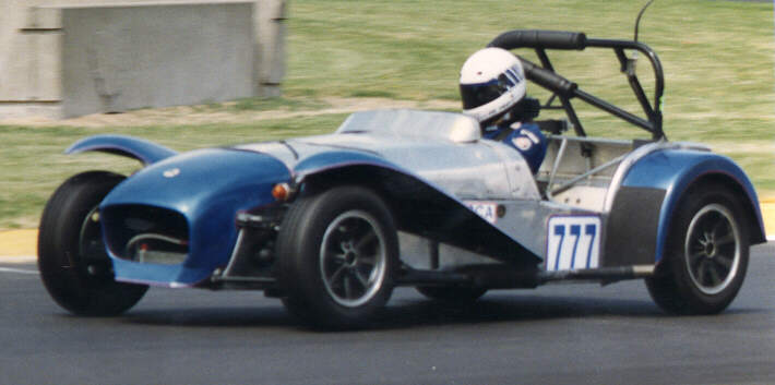
Here I am at the Portland International Raceway
(Portland Oregon). I used Seven S3 Dunlop 5.5 x 13 wheels and Mickey
Thompson bias belted 175/70-13 tires. Note the small air dam under the
nose. I fabricated a narrow racing seat to help support the upper body.
The aerial on the roll bar was a 2-way CB radio to the pits. The crew
could radio my lap times and position… in reality it was more of a
1-way communication, since most of my speech was heavily garbled by
ignition noise!
|